
YULIAN DWI WIDODO [4811010009]
JL. RAYA BOGOR RT02/09 NO 62. email: yulianwidodo@ymail.com
PRODI IT, JURUSAN ELEKTRO, POLITEKNIK NEGERI JAKARTA
KAMPUS BARU UI DEPOK, 16452
ABSTRACT
P55G is based on Nvidia chipset with Integrated GF7050/610i GPU which has up to 256MB Share Memory. By supporting Intel® Core™ 2 Quad* /Core™ 2 Duo / Celeron D processors and up to 1333MHz FSB, DDR2 800*, P55G can bring you the greatest value and enjoyment.
Premilinary
1. Background
A motherboard is the physical arrangement in a computer that contains the computer's basic circuitry and components. On the typical motherboard, the
circuitry is imprinted or affixed to the surface of a firm planar surface and usually manufactured in a single step. The most common motherboard design in desktop computers today is the AT, based on the IBM AT motherboard. A more recent motherboard specification, ATX, improves on the AT design2. Problem formulation
The problem is how to assemble a motherboard-VM PC CHIPS® P55G correctly and what the latest technology found in PC CHIPS motherboard ® P55G and there is any advantage in it.
3. purpose
The purpose of this study is that the reader can assemble this series with a good motherboard and can learn the latest technology and excellence motherboard series-VM PC CHIPS® P55G
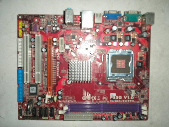
Label | COMPONENTS |
CPU soket | LGA775 intel® coretm2 processor Pentium 4 |
CPU FAN | CPU cooling fan connector |
DDR@_1-2 | 240-pin DDR2 SDRAM slot |
ATX_power | Standard 24-pin ATX power connector |
SYS_FAN | System cooling fan connector |
SATA1-4 | Serial ATA connector |
SPK | Speaker header |
LPT | Onboard parallel port header |
CLR_CMOS | Clear CMOS jumper |
F_PANEL | Font panel sw itch/LED header |
IDE | Primary IDE connector |
FDD | FLOPPY Disk Drive connector |
F_USB 1-2 | Front panel USB header |
USBPWR_F | Front panel USB power select Jumper |
CD_IN | Analog Audio Input header |
F_AUDIO | Front panel Audio Header |
PCI1-2 | 32-bit-add-on card slots |
SPDIFO | SPDIF out header |
PCIEX16 | PCI express slot for graphic interface |
PCIE | PCI express x1 slot |
USBPWR_R | Real panel USB PS/2 Power select jumper |
ATX12V | Auxiliary 4-pin power connector |
“*” Stand for motherboard is ready to support intel® coretm 2 Quad pentium® D/pentium® 4 processor and over spec to support list on PCCHIPS websiteI/O Port

Specification
· Processor : support intel® coreTM 2 Quad*/coreTM 2 Duo/Pentium® D*/Pentium® 4*Celeron® D processor whit front side Bus 1333/ 1066/800 and MHZ and Hyper-Threading Technology
· Chipset:NVIDIA® MCP73V (a single-chip)
Ø Support 33_bit addressing for access to 8GB of system memory
Ø PCI Express 16-lane link interface for external graphics processors
Ø PCI 2.3 interface at 33 MHz
Ø Fast ATA-133 IDE controller
· Memory :two 240-pin DIMM sockets for DDR2 667/533 (over spec up to 800*), and maximum installed memory 4 GB
· Slots: One PCIE x 16 slot,one OCIE x1slot and two 32-bit PCI slots
· Onboard IDE channels: Integrated SATA Controller with maximum transfer rate up to 3.0 GB/s
· HD Audio codec : Compliant with high definition Audio codec
· Onboard I/O ports: Two PS/2 ports for mouse and keyboard , one serial port , one VGA port , one LAN port, for back-panel USB2.0 port and three audio jacksfr microphone, line-in and line-out
· Fast Ethernet LAN : compliant with Universal serial Bus specification revision 2.0
Note 1: “*” Stand for motherboard is ready to support intel® coretm 2 Quad entium® D/entium® 4 processor and over spec to support list on PCCHIPS website Note 2 : t reach DDR2 800, please make sure that “ system clock Mode” in “Frequensy/Voltage Control” should select to “ Unlinked ” manually since the Auto-run is DDR2 667. |
Package contents
Your motherboard package ships with the following items :
~ The Motherboard
~ The Quick installation Guide
~ One diskette drive ribbon cable (optional)
~ One IDE drive ribbon cable
~ The software support CD
Note : Hardware specification and software Item are subject to change without notification |
CPU installation
Follow these instructions to install the CPU:
A. Read and follow the instruction shown on the sticker on the cap
B. Unload the cap
· Use thumb & forefinger to hold the lifting tab of the cap
· Lift the cap up and remove the cap completely from the soket
C. Open the load plate
· Use thumb & forefinger to hold the hook of the lever, pushing down and pulling down aside unlock plate
D. Install the CPU on the socket
· Orientate CPU package to the socket. Make sure you match triangle marker to pin 1 location.
E. Close the load plate
· Slightly push down the load plate onto the tongue side, and hook the laver.
· CPU is locked completely.
F. Apply thermal grease on top of the CPU.
G. Fasten the cooling fan supporting base onto the CPU socked on the motherboard.
H. Make sure the CPU fan is plugged to the CPU cooling fan user’smanual for mare detail installation procedure.
Note 1 : To achieve better airflow rates and heat dissipation, we suggest that you use a high quality fan with 3800 rpm at least CPU fan and heatsink installation procedures may vary with the heatsink may also vary. Note 2 : The fan connector supports the CPU cooling fan of 1.1A-2.2A (26.4W max) at + 12 V. Note 3 : DO NOT remove the CPU cap from the socket before installing a CPU. Note 4 : Return Material Authorization (RMA) requests will be accepted only if the motherboard comes with the cap on the LGA775 socket. |
Memory Module installation
1. Push down the latches on both sides of the DIMM socket, aligning the memory module with the socket, matching the module cutout with socket notch.
2. Install the DIMM module into the socket and press it firmly down until it is seated correctly. Socked latches are laveered upwards and latch on to edges of the DIMM.
Jumper Setting
Connecting two pins with a jumper cap is SHORT; removing a jumper cap from these pins, OPEN.
CLR_CMOS: Clear CMOS jumper
You may need to clear the CMOS memory if the settings in the setup Untility are incorrect and prevent your motherboard from operating. To clear the CMOS memory, disconnect all the power cables from the motherboard and then move the jumper cap into the CLEAR setting for a few seconds.

FUNCTION | Jumper setting |
Normal | Short Pins 1-2 |
Clear CMOS | Short Pins 2-3 |
Note : “ Bold white line” on the motherboard indicates Pin1. 2. Before installing this motherboard, make sure jumper CLR_CMOS1 is under normal setting. 3. To avoid the system unstability after clearing CMOS, we recommend users to enter the ,main BIOS setting page to “load Optimal Defaults “and then” save changes and exit |
USB PWR_F : FRONT PANEL USB POWER SELECT jumper
Use this jumper to se the Front panel USB power function.
Function | Jumper Setting |
VCC | Short Pins 1-2 |
5VSB | Short Pins 2-3 |
USBPWR_R: REAR USB PS/2 POWER SELECT jumper
Use this jumper to set the Rear USB PS/2 Power function.
FUNCTION | Jumper setting |
VCC | Short Pins 1-2 |
5VSB | Short Pins 2-3 |
Note : 1. Make sure the power supply provides enough SB5V voltage before selecting the SB5G function 2. To make up the computer by USB/PS2 KN/mouse in S3 status, pin instead of 1-2 as default, and then press into BIOS “ Power management Setup” page to choose the functions (USBPS2/KB/MS) you want to enable. |
Connectors and Headers
F_PANEL Connect the case switches and indicator LEDs to the F_PANEL Header.
F_AUDIO is for installing auxiliary front-oriented microphone and line-out ports.
FUSB1-2 Use Auxiliary USB headers F_USB1-2, if your computer case has USB ports at the front of the case.
LPT This is an onboard parallel port header that be used to connect to the printer, scanner or other devices.
SPDIFO This is an optional header that provides an SPDIFO (sony/Philips Digital interface) output to digital multimedia device through optical fiber of coaxial connector.
SPK connect the cable from the PC speaker to the SPK header.
HDD Use the floppy disk drive cable to connect the drives with the FDD connector.
IDE Use the IDE cable(s) to connect IDE primary device with the IDE channel connector IDE (primary).
SATA1-4 if you installed Series ATA hard drive, you can connect the serial ATA cables to the Serial ATA hard drive or the connector.
CD_IN Use this connector CD_IN to connect the drive audio cable to the installed a CD_ROM or DVD_ROM drive.
CPU_FAN connect the CPU cooling fan cabe to CPU fan connector (CPU_FAN).
SYS_FAN Connector the cable from the cooling fan to the SYS_FAN fan power connector.
ATX12V the ATX12V is a +12V connector for CPU Vcore power.
ATX_POWER Connector the power connector from the power supply to the ATX_POWER connector.
Note: Please refer to the Motherboard componens page for loacations of jumpers, headers and connectors. The whole User’s Guide in the bundled CD can provide you with detailed pin definitions of all componnents. |
BIOS Setup Utility
The BIOS setup Utility record setting and information of your computer. If the system malfunction happens for incorrect Setup Utility configuration, you can use the clear CMOS jumper to clear he CMOS memory, or hold down the Page up key while rebooting your computer. Holding down the Page down key also clears the setup the configuration.
Software & Applications
The support SD_ROM contains all useful software, necessary drivers and utility programs to properly run our products. Simply insert the support CD into and then you can go on auto-installing.


0 comments:
Posting Komentar
positive comments and if you liked my post, please given a rating. thank you